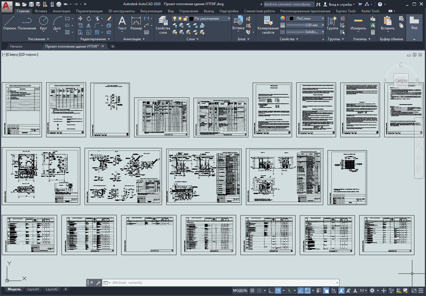
Project of heating of the building UPTIG
Sold 0
Refunds 0
Good feedbacks 0
Bad feedbacks 0
Working project of heating and ventilation of the UPTIG building.
The building is equipped with a central water heating system and a heat supply system of the P1 supply unit.
The heating system is intended to be a standby system and, when the ventilation system is switched off, ensures the maintenance of the minimum permissible indoor air temperature of 5°C.
The estimated indoor air temperature of 10°C is ensured by the combined operation of the heating system and the supply ventilation system, which provides additional heat input to the PTPIG room due to overheating of the supply air by 6°C.
The heating system is single-pipe, with upper wiring and dead-end movement of the coolant.
Heating devices in the heating system are registers made of smooth electric-welded pipes according to
The heat supply system of the air heaters is made according to the classical scheme, ensuring quantitative regulation of heat release.
To empty the heating and heat supply systems, a water collection sump is provided in the supply ventilation chamber room, where the control unit is located. Water removal from the pit is provided by a BKF-4 hand pump to the building's blind area.
Solutions for ventilation of the UPTIG premises:
The building is equipped with a supply ventilation system with mechanical inducement, exhaust general ventilation systems with natural inducement and an emergency exhaust ventilation system with mechanical inducement
File format: dwg, tif (AutoCAD 2010 is not editable)
Note: the original *.tif files must be in the same folder with the *.dwg project file
Download the file "Heating project of the UPTIG building" >>>
Tags: gas compressor station, UPTIG
