Compressor installation project
Sold 2
Refunds 0
Good feedbacks 0
Bad feedbacks 0
Working project for the installation of compressors at a thermal power plant.
Replacing piston compressors with screw compressors involves the dismantling of the existing foundations of piston compressors, with the arrangement of foundations for newly installed screw compressors, the organization of openings in the walls with the strengthening of building structures with frames made of rolled profiles, the installation of support structures for air ducts.
The installation is supposed to be screw compressors U-75 with a capacity of 75 kW, which have a capacity of up to 10.92 m3/min and create a pressure of at least 8 kgf/cm2.
Technical re-equipment will be carried out on the territory of the CHPP in the premises of the compressor station.
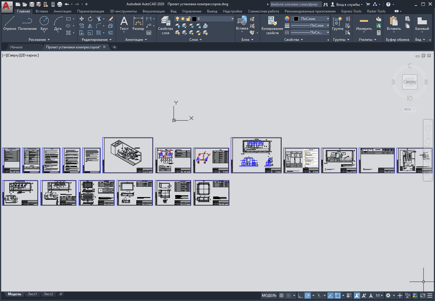
Working drawings for the installation of screw compressors:
1. General data.
2. General view of U-75 screw compressors.
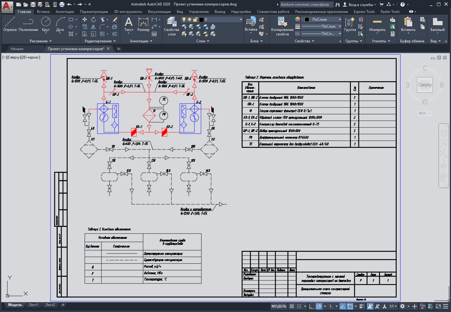
3. Schematic diagram of the compressor station.
4. Scheme of air boxes and pipelines of the compressor station.
5. Plan of air ducts and pipelines of the compressor station.
6. Schematic diagram of a single-line power supply for compressors.
7. Plan of cable routes.
8. Cable magazine.
9. Scheme of reconstruction of the compressor room at el. 0.000.
10. Layout of foundations and structural elements at el. 0.000 .
11. Specification of equipment, products and materials.
Format - DWG compatible with AutoCAD 2004-2017, Compass, ZWCAD, nanoCAD, BricsCAD, etc.

